Case 1
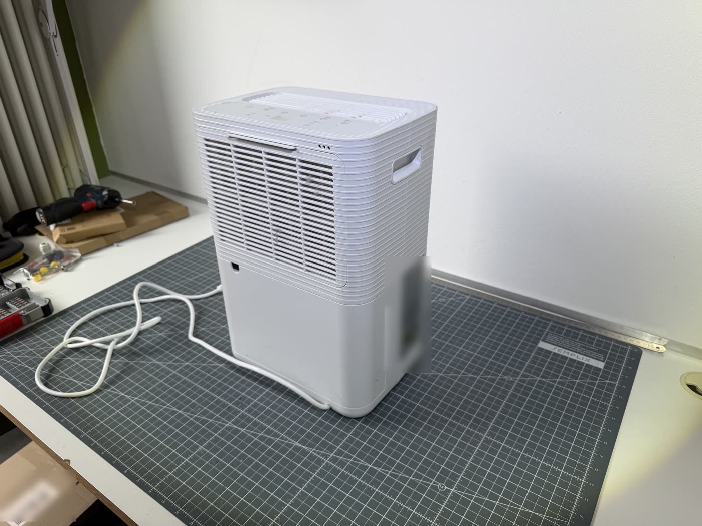
A dehumidifier.
An appliance that caused a fire. A test report declaring every component passed. And our own tests on exactly those materials. Placed side by side, the three show what the standard route of proof delivers and what it does not.
What was left
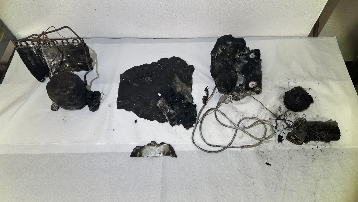
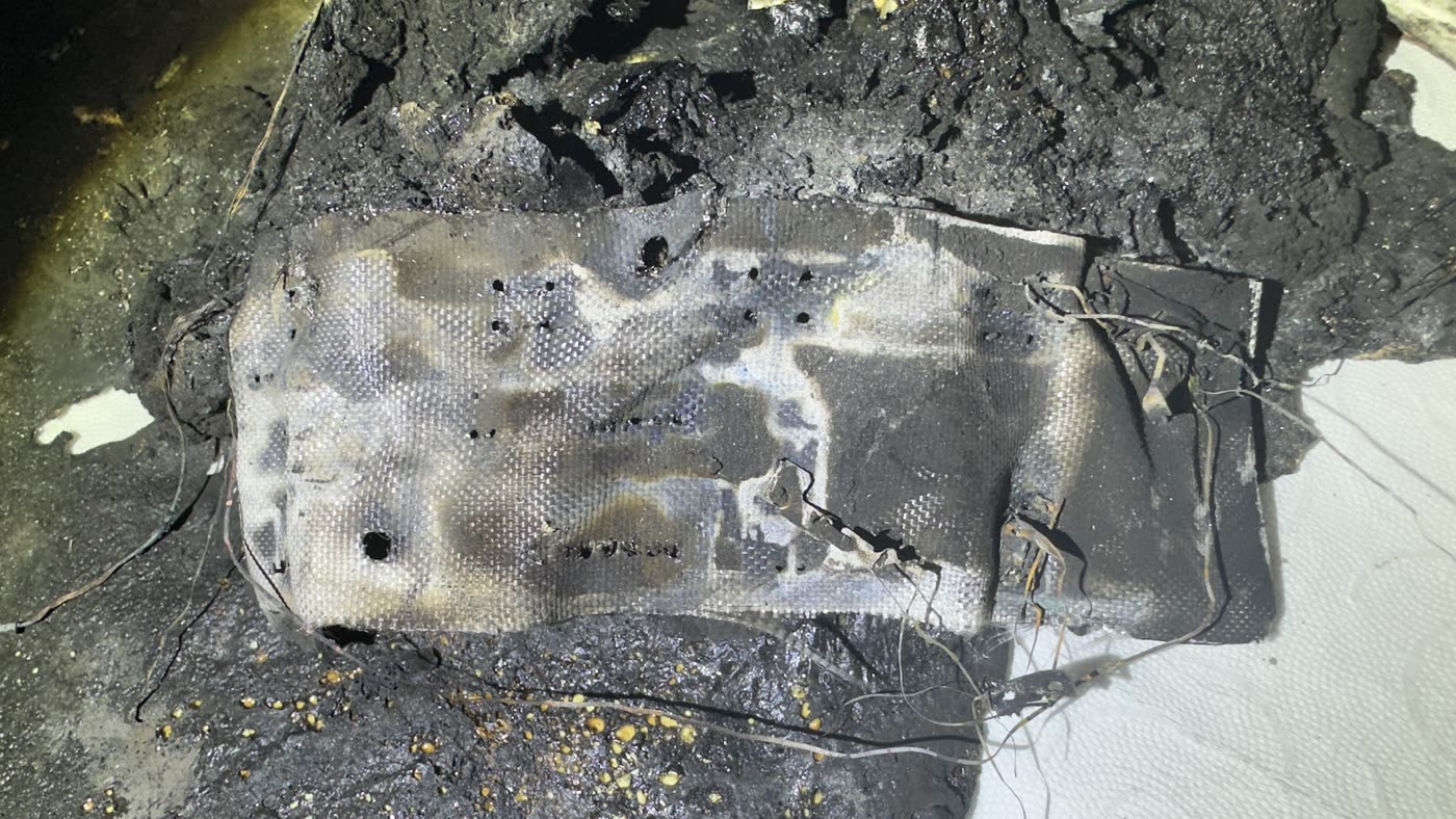
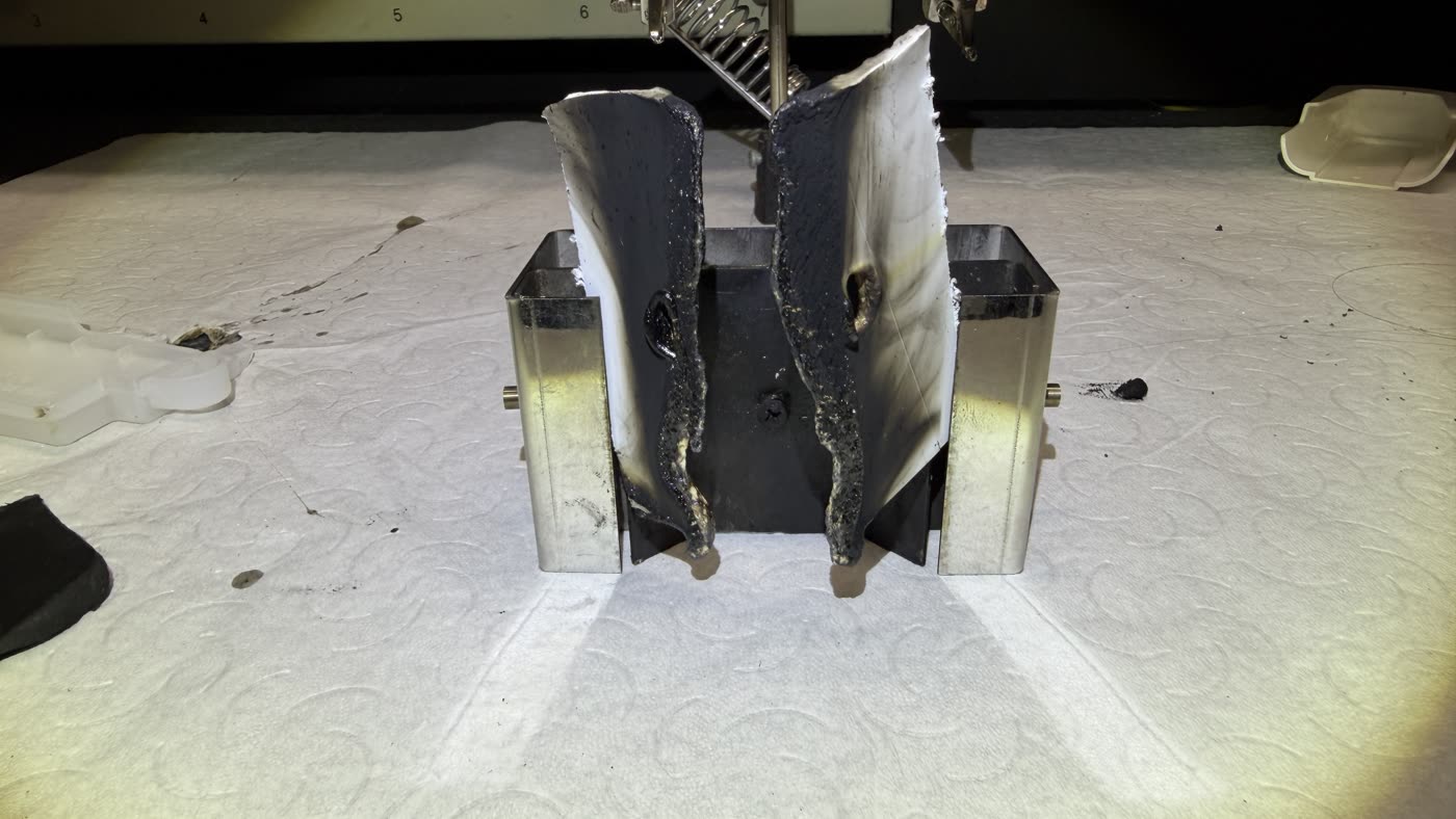
On the expert finding, the appliance is where the fire originated. The remains were secured at the scene. The photograph shows the recovered components: heat exchanger, compressor, remains of the enclosure, the mains lead and what was left of the electronics.
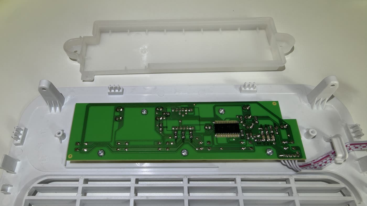
The state of the display electronics stands out. It carries little power, and for that very reason it is widely regarded as a component from which no fire originates. What remains is a completely destroyed assembly.
The assumed sequence
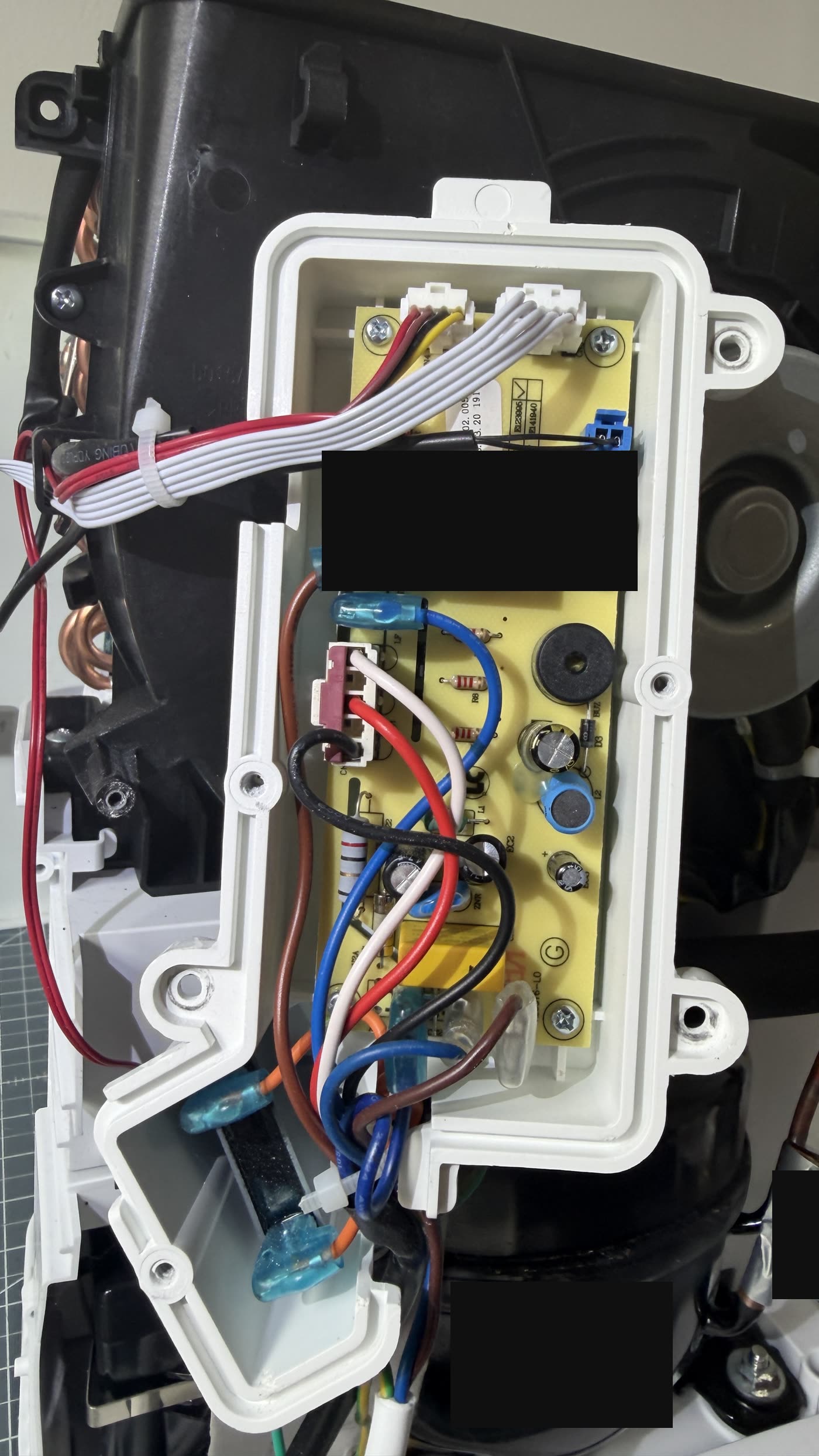
On the findings, the starting point lies in the power supply unit. The failure of a component there led to a rise in voltage on the secondary side. This voltage overloaded the electronics of the control unit; a capacitor probably ignited in the process.
What determined the extent of the damage, however, was not the ignition source but what it found: the electronics sit directly in combustible plastic. The housing of the power supply is harder to ignite but continues to burn on its own once alight.
A second finding in the design
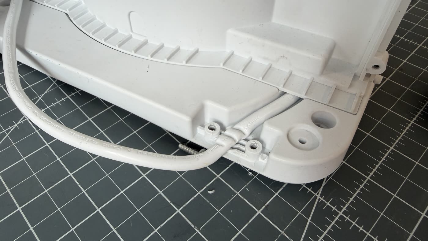
Independently of this, the comparison appliance revealed a design defect. In the strain relief, the mains lead is compressed so severely that a fire hazard can arise from it.
The combination is what matters: a possible ignition source lies directly against readily combustible plastic. It is precisely this proximity that the selection diagram of the test standard is meant to capture through the term immediate vicinity.
What the test report records
A test report on Clause 30.2 exists for the appliance. It lists the components individually, with the test temperature chosen and the result. Two columns are decisive: whether the specimen ignited, and whether it extinguished within 30 seconds after the wire was withdrawn.
The enclosure parts were tested at 550 °C, other components at 650, 750 and 850 °C. In almost every row, the ignition column reads no. Where nothing ignited, the extinguishing column reads “N/A” — not applicable. The result in every row is: pass.
One single row stands apart. Where a component did ignite at 850 °C, extinguishing was tested and confirmed. It is the only row containing a genuine measured value for the second property.
| Component | Test temperature | Self-ignition | Extinguished in 30 s | Drops ignite tissue | Result |
|---|---|---|---|---|---|
| Plastic enclosure | 550 °C | no | n/a | n/a | pass |
| Main board box | 550 °C | no | n/a | n/a | pass |
| Bobbin of fan motor | 550 °C | no | n/a | n/a | pass |
| Control PCB box | 550 °C | no | n/a | n/a | pass |
| Control panel | 550 °C | no | n/a | n/a | pass |
| Component | Test temperature | Self-ignition | Extinguished in 30 s | Drops ignite tissue | Result |
|---|---|---|---|---|---|
| Top cover | 550 °C | no | n/a | n/a | pass |
| X capacitor | 650 °C | no | n/a | n/a | pass |
| Water level sensor | 650 °C | no | n/a | n/a | pass |
| Running capacitor, fan motor | 750 °C | no | n/a | n/a | pass |
| Running capacitor, fan motor | 850 °C | no | n/a | n/a | pass |
| Relay | 750 °C | no | n/a | n/a | pass |
| Relay | 850 °C | no | n/a | n/a | pass |
| Terminal connector on PCB | 750 °C | no | n/a | n/a | pass |
| Terminal connector on PCB | 850 °C | yes | yes | n/a | pass |
| Tube on main board | 750 °C | no | n/a | n/a | pass |
The only row with a measured value for the second property: at 850 °C the component ignited, and only there was extinguishing actually examined.
“n/a” in the report stands for “not applicable”. The criterion was not examined because the specimen did not ignite.
Reproduction of the content of the test report entries on Clause 30.2. The data are taken from the report; the presentation is our own. The issuing body, the manufacturer and the file reference are not named.
Where nothing ignites, nothing is measured. The result is a pass all the same.
Our own tests on the same materials
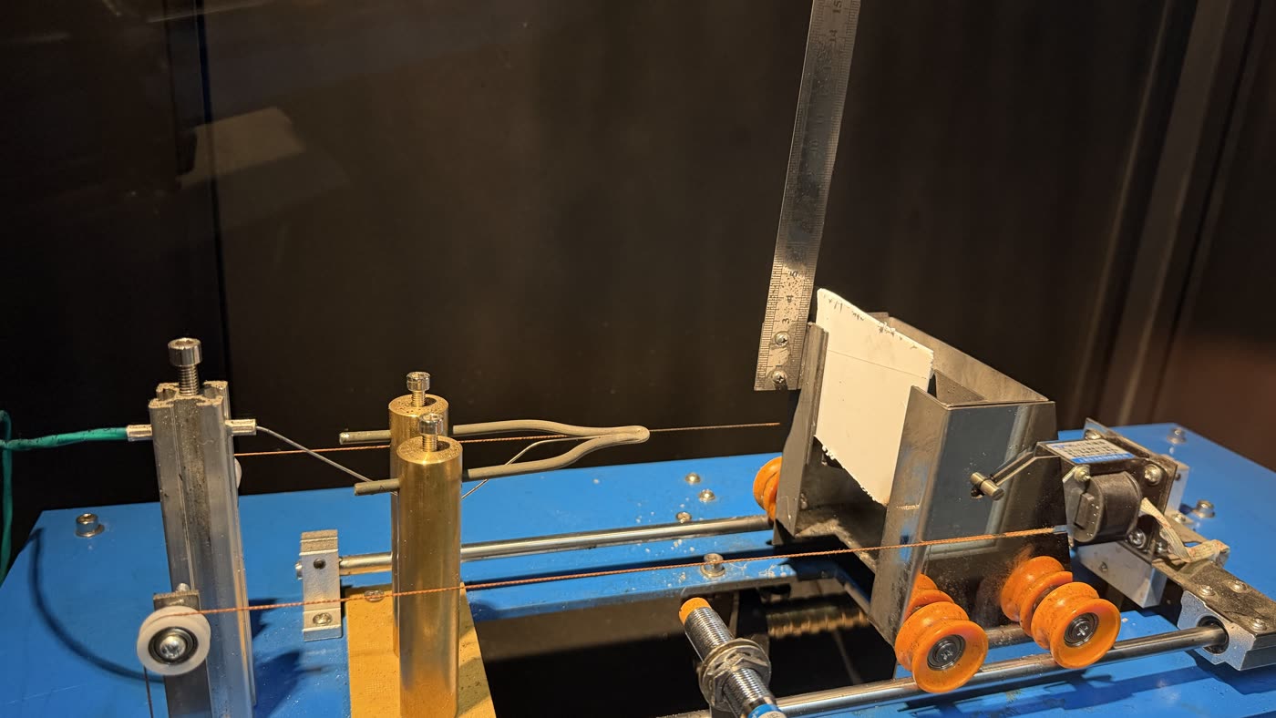
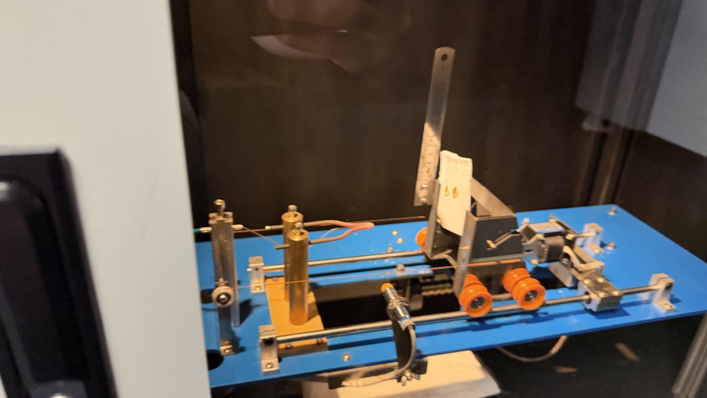
Material samples were taken from the comparison appliance and tested: once with the needle flame, once with the glow wire at rising temperatures. The recordings are uncut and without sound.
With the flame
Under the needle flame all three samples tested burn. The white sample burns, the transparent one burns and drips like paraffin, the black one likewise.
White plastic
Transparent plastic
Black plastic
With the glow wire
With the glow wire a different picture emerges. It depends on the material and on the temperature — and in one case the material does not ignite at any level.
Milky plastic
No ignition at any of the four levels, not even at 850 °C.
550 °C
650 °C
750 °C
850 °C
White plastic
No ignition at 550 and 650 °C. At 750 °C it begins to burn.
550 °C
650 °C
750 °C
Black enclosure plastic
No ignition at 650 and 750 °C. Only at 850 °C does it begin to burn.
650 °C
750 °C
850 °C
What the case shows
- The enclosure components were tested at 550 °C and passed. In our own tests none of the samples examined ignited at that temperature.
- Where no ignition occurred in the report, resistance to the spread of fire is recorded as not applicable. It was not measured there.
- In our own tests all the materials examined burn under the needle flame. Under the glow wire one material ignites from 750 °C, another from 850 °C.
- One sample did not ignite at any of the four levels tested up to and including 850 °C. Even the high levels are therefore no reliable proof.
- On the expert finding the fire originated in the appliance, and it did not remain confined to where it started.
The test report is correct. It simply says nothing about what happened here.
This case establishes no rate and no series. It shows, in a documented example, how the standard route of proof works and where its statement ends. No conclusion about other appliances, from this or any other manufacturer, follows from it.